The Ammeter in the Figure Reads 3.0 a. (Figure 1)
Learning Objectives
Past the end of this section, yous will be able to:
- Explain why a voltmeter must exist continued in parallel with the circuit.
- Draw a diagram showing an ammeter correctly connected in a circuit.
- Depict how a galvanometer can be used as either a voltmeter or an ammeter.
- Find the resistance that must exist placed in serial with a galvanometer to allow it to be used as a voltmeter with a given reading.
- Explain why measuring the voltage or current in a circuit can never be verbal.
Voltmeters measure voltage, whereas ammeters measure out current. Some of the meters in automobile dashboards, digital cameras, cell phones, and tuner-amplifiers are voltmeters or ammeters. (See Figure 1.) The internal construction of the simplest of these meters and how they are connected to the arrangement they monitor give further insight into applications of series and parallel connections.
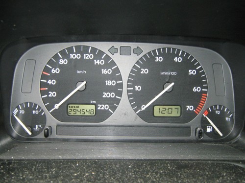
Figure 1. The fuel and temperature gauges (far correct and far left, respectively) in this 1996 Volkswagen are voltmeters that register the voltage output of "sender" units, which are hopefully proportional to the corporeality of gasoline in the tank and the engine temperature. (credit: Christian Giersing)
Voltmeters are connected in parallel with whatever device'due south voltage is to exist measured. A parallel connectedness is used considering objects in parallel experience the same potential difference. (See Effigy 2, where the voltmeter is represented by the symbol V.) Ammeters are connected in serial with whatever device's current is to be measured. A series connection is used because objects in serial accept the aforementioned current passing through them. (See Figure 3, where the ammeter is represented by the symbol A.)
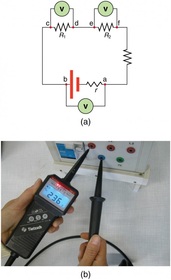
Figure 2. (a) To measure potential differences in this series excursion, the voltmeter (V) is placed in parallel with the voltage source or either of the resistors. Annotation that terminal voltage is measured between points a and b. Information technology is not possible to connect the voltmeter direct across the emf without including its internal resistance, r. (b) A digital voltmeter in use. (credit: Messtechniker, Wikimedia Commons)
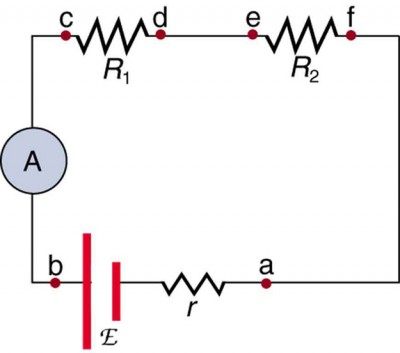
Figure iii. An ammeter (A) is placed in series to mensurate electric current. All of the current in this excursion flows through the meter. The ammeter would have the same reading if located betwixt points d and eastward or between points f and a as it does in the position shown. (Note that the script majuscule East stands for emf, and r stands for the internal resistance of the source of potential difference.)
Analog Meters: Galvanometers
Analog meters take a needle that swivels to point at numbers on a calibration, as opposed to digital meters, which have numerical readouts similar to a hand-held calculator. The heart of most analog meters is a device chosen a galvanometer, denoted past Chiliad. Current catamenia through a galvanometer, I G, produces a proportional needle deflection. (This deflection is due to the force of a magnetic field upon a current-carrying wire.)
The two crucial characteristics of a given galvanometer are its resistance and current sensitivity. Current sensitivity is the electric current that gives a full-scale deflection of the galvanometer's needle, the maximum electric current that the musical instrument can measure. For case, a galvanometer with a current sensitivity of 50 μA has a maximum deflection of its needle when 50 μA flows through it, reads half-scale when 25 μA flows through it, then on. If such a galvanometer has a 25-Ω resistance, then a voltage of simply5 = IR = (fifty μA)(25 Ω) = 1.25 mV produces a total-scale reading. Past connecting resistors to this galvanometer in different ways, you can use it as either a voltmeter or ammeter that can measure a broad range of voltages or currents.
Galvanometer as Voltmeter
Effigy 4 shows how a galvanometer can be used as a voltmeter by connecting it in series with a large resistance, R. The value of the resistance R is adamant by the maximum voltage to be measured. Suppose you want 10 V to produce a full-calibration deflection of a voltmeter containing a 25-Ω galvanometer with a 50-μA sensitivity. Then 10 V applied to the meter must produce a electric current of 50 μA. The total resistance must be
[latex]{R}_{\text{tot}}=R+r=\frac{V}{I}=\frac{10\text{ V}}{50\text{ }\mu \text{A}}=200\text{ yard}\Omega\\[/latex] or
[latex]R={R}_{\text{tot}}-r=200\text{ k}\Omega-25\text{ }\Omega \approx 200\text{ k}\Omega \\[/latex].
(R is and so large that the galvanometer resistance, r, is nearly negligible.) Annotation that 5 V applied to this voltmeter produces a half-scale deflection past producing a 25-μA current through the meter, and so the voltmeter's reading is proportional to voltage equally desired. This voltmeter would non exist useful for voltages less than nigh one-half a volt, because the meter deflection would be small and difficult to read accurately. For other voltage ranges, other resistances are placed in series with the galvanometer. Many meters have a choice of scales. That choice involves switching an advisable resistance into series with the galvanometer.
Figure iv. A large resistance R placed in serial with a galvanometer Thousand produces a voltmeter, the full-calibration deflection of which depends on the option of R. The larger the voltage to be measured, the larger R must be. (Notation that r represents the internal resistance of the galvanometer.)
Galvanometer equally Ammeter
The same galvanometer can also be fabricated into an ammeter past placing it in parallel with a small resistance R, ofttimes called the shunt resistance, as shown in Figure 5. Since the shunt resistance is small, most of the current passes through it, assuasive an ammeter to measure currents much greater than those producing a full-scale deflection of the galvanometer. Suppose, for example, an ammeter is needed that gives a total-scale deflection for 1.0 A, and contains the same 25-Ω galvanometer with its 50-μA sensitivity. Since R and r are in parallel, the voltage beyond them is the same. These IR drops areIR = I G r so that [latex]IR=\frac{{I}_{\text{M}}}{I}=\frac{R}{r}\\[/latex]. Solving for R, and noting that I 1000 is fifty μA and I is 0.999950 A, we have
[latex]R=r\frac{{I}_{\text{G}}}{I}=\left(25\text{ }\Omega\right)\frac{50\text{ }\mu\text{A}}{0.999950\text{ A}}=i.25\times 10^{-3}\text{ }\Omega\\[/latex].
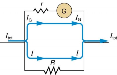
Figure v. A small shunt resistance R placed in parallel with a galvanometer G produces an ammeter, the full-scale deflection of which depends on the choice of R. The larger the current to exist measured, the smaller R must exist. Almost of the current (I) flowing through the meter is shunted through R to protect the galvanometer. (Note that r represents the internal resistance of the galvanometer.) Ammeters may also accept multiple scales for greater flexibility in application. The various scales are achieved by switching various shunt resistances in parallel with the galvanometer—the greater the maximum current to be measured, the smaller the shunt resistance must be.
Taking Measurements Alters the Circuit
When you use a voltmeter or ammeter, y'all are connecting some other resistor to an existing circuit and, thus, altering the excursion. Ideally, voltmeters and ammeters do non appreciably affect the circuit, just information technology is instructive to examine the circumstances nether which they exercise or do not interfere. Get-go, consider the voltmeter, which is always placed in parallel with the device being measured. Very little current flows through the voltmeter if its resistance is a few orders of magnitude greater than the device, and so the excursion is non appreciably affected. (See Figure six(a).) (A big resistance in parallel with a small one has a combined resistance substantially equal to the modest one.) If, still, the voltmeter'south resistance is comparable to that of the device being measured, then the two in parallel accept a smaller resistance, appreciably affecting the circuit. (Run into Effigy 6(b).) The voltage beyond the device is not the same every bit when the voltmeter is out of the circuit.
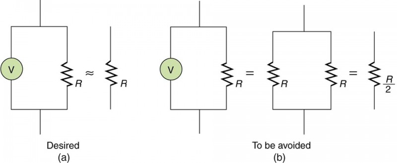
Figure 6. (a) A voltmeter having a resistance much larger than the device (RVoltmeter>>R) with which it is in parallel produces a parallel resistance substantially the aforementioned every bit the device and does not appreciably bear on the circuit being measured. (b) Hither the voltmeter has the same resistance as the device (RVoltmeter≅R), so that the parallel resistance is half of what it is when the voltmeter is not connected. This is an example of a significant alteration of the circuit and is to exist avoided.
An ammeter is placed in series in the branch of the excursion being measured, so that its resistance adds to that branch. Normally, the ammeter'southward resistance is very small compared with the resistances of the devices in the circuit, and and so the extra resistance is negligible. (See Figure seven(a).) Yet, if very pocket-size load resistances are involved, or if the ammeter is not as low in resistance as it should exist, and so the total serial resistance is significantly greater, and the electric current in the branch being measured is reduced. (See Effigy seven(b).) A practical trouble can occur if the ammeter is continued incorrectly. If information technology was put in parallel with the resistor to measure the current in it, you could possibly impairment the meter; the low resistance of the ammeter would allow about of the electric current in the circuit to go through the galvanometer, and this current would be larger since the constructive resistance is smaller.
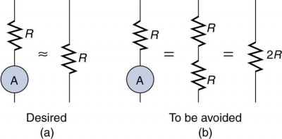
Figure 7. (a) An ammeter normally has such a small resistance that the total series resistance in the branch being measured is not appreciably increased. The circuit is essentially unaltered compared with when the ammeter is absent. (b) Hither the ammeter's resistance is the same every bit that of the branch, so that the total resistance is doubled and the electric current is half what it is without the ammeter. This significant amending of the circuit is to exist avoided.
One solution to the problem of voltmeters and ammeters interfering with the circuits beingness measured is to use galvanometers with greater sensitivity. This allows construction of voltmeters with greater resistance and ammeters with smaller resistance than when less sensitive galvanometers are used. There are practical limits to galvanometer sensitivity, simply information technology is possible to get analog meters that make measurements accurate to a few percent. Annotation that the inaccuracy comes from altering the circuit, not from a fault in the meter.
Connections: Limits to Knowledge
Making a measurement alters the organisation beingness measured in a manner that produces uncertainty in the measurement. For macroscopic systems, such as the circuits discussed in this module, the amending tin usually be made negligibly small, merely it cannot be eliminated entirely. For submicroscopic systems, such as atoms, nuclei, and smaller particles, measurement alters the system in a manner that cannot be fabricated arbitrarily small. This actually limits knowledge of the system—even limiting what nature tin can know about itself. We shall come across profound implications of this when the Heisenberg doubtfulness principle is discussed in the modules on breakthrough mechanics.
There is another measurement technique based on drawing no current at all and, hence, not altering the circuit at all. These are called null measurements and are the topic of Null Measurements. Digital meters that employ solid-state electronics and null measurements tin can attain accuracies of one part in tenhalf-dozen.
Check Your Understanding
Digital meters are able to find smaller currents than analog meters employing galvanometers. How does this explain their power to measure voltage and electric current more accurately than analog meters?
Solution
Since digital meters require less current than analog meters, they alter the circuit less than analog meters. Their resistance as a voltmeter can exist far greater than an analog meter, and their resistance as an ammeter can be far less than an analog meter. Consult Figure 2 and Effigy 3 and their give-and-take in the text.
PhET Explorations: Circuit Structure Kit (DC Merely), Virtual Lab
Stimulate a neuron and monitor what happens. Pause, rewind, and move forward in fourth dimension in order to find the ions as they move across the neuron membrane.

Click to download the simulation. Run using Java.
Section Summary
- Voltmeters measure voltage, and ammeters measure out current.
- A voltmeter is placed in parallel with the voltage source to receive full voltage and must have a large resistance to limit its issue on the circuit.
- An ammeter is placed in serial to get the full current flowing through a co-operative and must have a modest resistance to limit its upshot on the circuit.
- Both tin be based on the combination of a resistor and a galvanometer, a device that gives an analog reading of current.
- Standard voltmeters and ammeters modify the excursion being measured and are thus limited in accuracy.
Conceptual Questions
1. Why should you not connect an ammeter direct across a voltage source equally shown in Figure 9? (Notation that script Eastward in the figure stands for emf.)
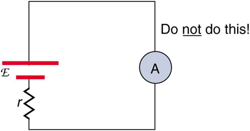
Effigy 9.
ii. Suppose you are using a multimeter (one designed to measure a range of voltages, currents, and resistances) to measure current in a circuit and you lot inadvertently leave information technology in a voltmeter mode. What effect will the meter have on the excursion? What would happen if you lot were measuring voltage but accidentally put the meter in the ammeter mode?
3. Specify the points to which you could connect a voltmeter to mensurate the post-obit potential differences in Figure x: (a) the potential difference of the voltage source; (b) the potential divergence across R ane; (c) acrossR ii; (d) beyondR 3; (due east) acrossR two andR 3. Notation that at that place may exist more than than i answer to each office.

Figure 10.
4. To measure currents in Figure 10, you would supervene upon a wire between 2 points with an ammeter. Specify the points between which you would place an ammeter to measure the following: (a) the total electric current; (b) the current flowing throughR 1; (c) throughR ii; (d) throughR iii. Note that there may exist more than one answer to each part.
Issues & Exercises
1. What is the sensitivity of the galvanometer (that is, what current gives a full-calibration deflection) inside a voltmeter that has a 1.00-MΩ resistance on its 30.0-Five scale?
2. What is the sensitivity of the galvanometer (that is, what electric current gives a total-scale deflection) within a voltmeter that has a 25.0-kΩ resistance on its 100-V scale?
3. Find the resistance that must exist placed in series with a 25.0-Ω galvanometer having afifty.0 -μA sensitivity (the same as the ane discussed in the text) to permit it to exist used every bit a voltmeter with a 0.100-V full-scale reading.
4. Detect the resistance that must be placed in series with a25 . 0-Ω galvanometer having a50.0 -μA sensitivity (the same as the 1 discussed in the text) to allow it to be used every bit a voltmeter with a 3000-V full-scale reading. Include a circuit diagram with your solution.
5. Find the resistance that must be placed in parallel with a25 . 0-Ω galvanometer having a50.0 -μA sensitivity (the same as the one discussed in the text) to let it to be used as an ammeter with a ten.0-A full-scale reading. Include a circuit diagram with your solution.
six. Observe the resistance that must exist placed in parallel with a25 . 0-Ω galvanometer having a50.0 -μA sensitivity (the same as the one discussed in the text) to permit information technology to exist used as an ammeter with a 300-mA full-scale reading.
7. Observe the resistance that must be placed in series with a x.0-Ω galvanometer having a 100-μA sensitivity to allow it to exist used as a voltmeter with: (a) a 300-Five total-scale reading, and (b) a 0.300-V full-scale reading.
eight. Find the resistance that must be placed in parallel with a 10.0-Ω galvanometer having a 100-μA sensitivity to permit information technology to be used every bit an ammeter with: (a) a 20.0-A full-scale reading, and (b) a 100-mA total-scale reading.
nine. Suppose you measure the last voltage of a i.585-V element of group i jail cell having an internal resistance of 0.100Ω by placing a ane.00-kΩ voltmeter across its terminals. (See Figure 11.) (a) What electric current flows? (b) Discover the terminal voltage. (c) To run into how shut the measured terminal voltage is to the emf, summate their ratio.

Figure 11.
10. Suppose y'all measure the terminal voltage of a three.200-V lithium cell having an internal resistance of five.00 Ω past placing a one.00-kΩ voltmeter across its terminals. (a) What current flows? (b) Find the terminal voltage. (c) To come across how close the measured terminal voltage is to the emf, summate their ratio.
11. A certain ammeter has a resistance of five.00 × 10−5Ω on its 3.00-A scale and contains a ten.0-Ω galvanometer. What is the sensitivity of the galvanometer?
12. A 1.00-MΩ voltmeter is placed in parallel with a 75.0-kΩ resistor in a circuit. (a) Describe a circuit diagram of the connection. (b) What is the resistance of the combination? (c) If the voltage across the combination is kept the aforementioned as it was beyond the 75.0-kΩ resistor solitary, what is the percent increase in current? (d) If the electric current through the combination is kept the same as it was through the 75.0-kΩ resistor alone, what is the percentage subtract in voltage? (e) Are the changes found in parts (c) and (d) pregnant? Hash out.
thirteen. A 0.0200-Ω ammeter is placed in series with a 10.00-Ω resistor in a excursion. (a) Draw a circuit diagram of the connection. (b) Calculate the resistance of the combination. (c) If the voltage is kept the same across the combination every bit it was through the 10.00-Ω resistor lone, what is the percent decrease in current? (d) If the electric current is kept the same through the combination as it was through the ten.00-Ω resistor alone, what is the percent increase in voltage? (e) Are the changes constitute in parts (c) and (d) significant? Discuss.
14. Unreasonable ResultsSuppose yous take a40.0-Ω galvanometer with a 25.0-μA sensitivity. (a) What resistance would you put in serial with information technology to allow it to be used equally a voltmeter that has a full-scale deflection for 0.500 mV? (b) What is unreasonable nearly this result? (c) Which assumptions are responsible?
xv. Unreasonable Results(a) What resistance would you put in parallel with a forty.0-Ω galvanometer having a 25.0-μA sensitivity to allow it to be used equally an ammeter that has a full-scale deflection for 10.0-μA? (b) What is unreasonable about this event? (c) Which assumptions are responsible?
Glossary
- voltmeter:
- an instrument that measures voltage
- ammeter:
- an instrument that measures current
- analog meter:
- a measuring instrument that gives a readout in the form of a needle move over a marked gauge
- digital meter:
- a measuring instrument that gives a readout in a digital form
- galvanometer:
- an analog measuring device, denoted by One thousand, that measures current flow using a needle deflection caused past a magnetic field strength acting upon a current-carrying wire
- electric current sensitivity:
- the maximum electric current that a galvanometer tin can read
- full-calibration deflection:
- the maximum deflection of a galvanometer needle, also known as current sensitivity; a galvanometer with a full-calibration deflection of 50 μA has a maximum deflection of its needle when 50 μA flows through it
- shunt resistance:
- a small resistance R placed in parallel with a galvanometer G to produce an ammeter; the larger the current to be measured, the smallerR must be; near of the current flowing through the meter is shunted throughR to protect the galvanometer
Selected Solutions to Issues & Exercises
1. 30 μA
3. 1 . 98 k Ω
5. 1 . 25 × 10 − 4 Ω
7. (a) 3.00 MΩ (b) ii.99 kΩ
9. (a) one.58 mA (b) one.5848 V (need iv digits to see the departure) (c) 0.99990 (need five digits to run across the deviation from unity)
eleven. 15 . 0 μA
12.
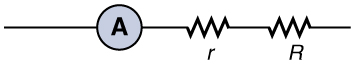
Figure 12.
(a)
(b) 10.02 Ω
(c) 0.9980, or a 2.0 × 10⁻¹ percent decrease
(d) one.002, or a ii.0 × ten–ane percent increment
(e) Not meaning.
15. (a) −66.7 Ω (b) You tin't have negative resistance. (c) It is unreasonable that I G is greater than I tot (see Effigy 5). You cannot attain a full-scale deflection using a current less than the sensitivity of the galvanometer.
Source: https://courses.lumenlearning.com/physics/chapter/21-4-dc-voltmeters-and-ammeters/